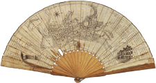
The pictorial field of vision and the optical devices
- Pictorial field of vision and the optical devices
- [click on the picture to enlarge it]

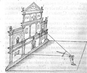
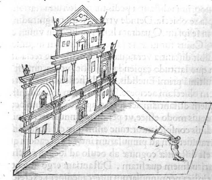
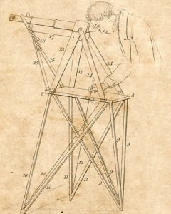
- Fig. 1.
- Rainer Gemma Frisius, De radio astronomico et geometrico liber, 1514, p. 21 verso.
[click on the picture to enlarge it]
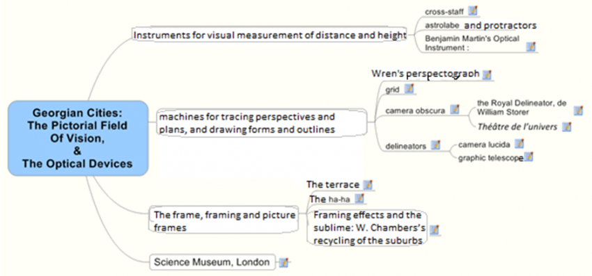
I. Instruments for visual measurement of distance and height
In order to measure distances on an area, as well as heights on façades, or their width, architects and artists resorted to the cross-staff [arbalestrille, ballastella], also called Jacob’s staff (Fig. 1.). The longer staff is graduated; the perpendicular rods slide across it, allowing the user to calculate the angles, and after trigonometrical calculations, to make all kinds of spatial measurements (distance, length, width or depth).
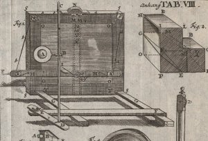
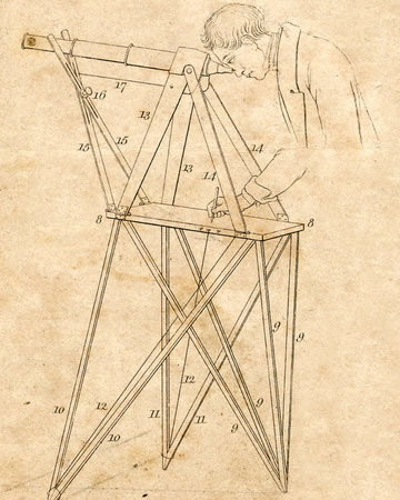
- Fig. 2.
- Camera obscura, grid, and cross-staff, from John Joshua Kirby, Dr. Brook Taylor’s Method of Perspective Made Easy, both in theory and practice; in two books... , 1765, Plate xviii B 2.
[click on the picture to enlarge it]

With astrolabes or various sorts of compasses, it was possible to make such calculations of angles. In 1755, the painter Joshua Kirby still show such a cross-staff in his Dr. Brook Taylor’s Method of Perspective Made Easy: both in Theory and Practice (fig. 2.).

- Fig. 3.
- Benjamin Martin, A New and Compendious System of Optics, 1740, p. 290, plate XXXIII.
[click on the picture to enlarge it]
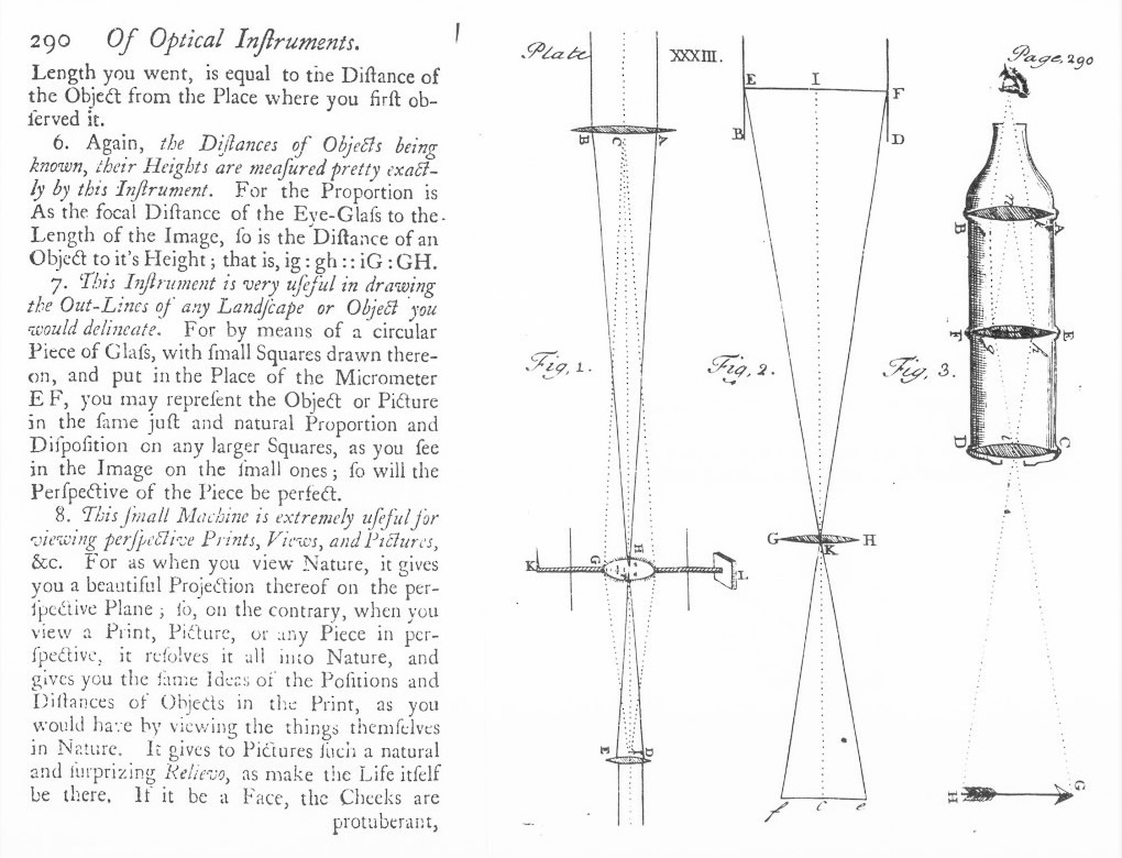
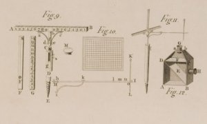
B. Benjamin Martin’s Optical Instrument:
(fig. 3.) This instrument is a kind of telescope where one of the lenses has been engraved with lines so as to produce a “Glass Micrometer” (E F) meant to measure distances and heights throuhg angular calculations.
It is mentioned in A New Compendious System of Optics (1740, p. 290) by Benjamin Martin. It is ‘An Optical Insturment for measuring the Angle of Vision, or estimating the apparent Magnitude of Bodies; also for viewing Perspective, Prints, Pictures, &c. ‘.
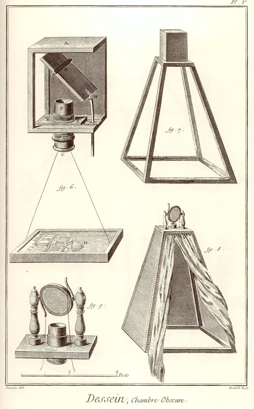
II. Machines for tracing perspectives and plans, and drawing forms and outlines
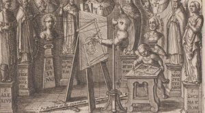
- Fig. 4.
- Christoph Scheiner, Pantographice seu ars Delineandi, 1631, frontispice (détail).
[click on the picture to enlarge it]
In the 17th century, the architect and anatomist Sir Christopher Wren invented an instrument ‘for drawing the Out- lines of any Object in Perspective’, whose workings were published in 1669.
It is derived from the pantograph, an apparatus meant to magnify or to reduce the object to be copied, by drawing with articulated rods arranged as a parallelogram (fig. 4. Scheiner fronstispice).
- Fig. 5.
- Nicolas Bion, Nicolaus Bions [...] neueröffnete mathematische Werkschule oder gründliche Anweisung, 1765, table VIII, detail of Wren’s perspectograph.
[click on the picture to enlarge it]

Wren’s version (fig. 5.) uses a system of pulleys and counterweights whcih make drawing more supple and less bumpy than a simple parallelogram positioned vertically on a painting.
- Fig. 6.
- Albrecht Dürer, Underweysung der Messung,1538, the drawing frame.
[click on the picture to enlarge it]
The first grid placed between the motif to be copied and the eye of the must be the one described by Leon Battista Alberti in 1435 in his treatise on painting De Pictura. This is also asserted by Vasari. This ‘intersector [...] is a veil of very thin threads, loosely woven, dyed in any colour, divided with thicker threads into as many strips of squares as you wish and stretched on a frame. I place it between the body to be represented and my eye, so that the visual pyramid penetrates the lights of the veil’.
The veil helps ‘circumscription’ – delineating the outlines of forms, and thus reducing three-dimensional volumes to two-dimensional silhouettes.
The grid process was brilliantly illustrated by Albrecht Dürer (fig. 6.), in an engraving known to all artists in England at the time, as shown by Joshua Kirby’s engraving (fig. 2.).
Moreover, it allowed squaring for enlargement, or anamorphosis to deform shapes, for any two- or three-dimensional object one needed to copy.
The principle of the camera obscura is fairly easy to explain: if, in a room plunged in obscurity, we pierce a small hole in a shutter or in a wall, the landscape or any scene or object placed outside in front of the hole, will be projected as images inside the room on to the wall or on any kind of screen opposite the opening. The nearer the screen is to the hole, the smaller, brighter and more precise the image will be; conversely, the more distant the screen, the larger, dull and blurred the image will be. However, whateve the distance of the screen, the image is inverted left-to-right and upside down, a double inversion due to the crossing of the light rays occurring when they pass through the hole. Finally, the shape of the hole does not alter at all the projected image, which depends only on the shape of the source of light. Thus, the shape of the sun remains circular even when its rays go through a keyhole or the leaves of trees, as Aristotle already remarked.
The principle of the camera obscura was originally used for astronomical observations, especially by mediaeval astronomers in order to study eclipses while preserving their eyesight from direct observation of the sun which would be dangerous for the ocular organs. Then, from the 16th century onwards, a second type of use of the camera became widespread: the apparatus was applied to the observation of the spectacle of daily life, in the country and much more often in the city.
Owing to the researches of Leonardo, the process of the camera obscura was then improved in two directions which proved decisve for painters.
The first type of techical modification, dating from the 16th century, affected the optical system. It consisted in adding a bi-convex converging lens placed in the orifice of the chamber, which significantly improves the quality of the image. The fairly obscure De Subtilitate by Cardano published in 1550 nonetheless testifies to the increased interest for street scenes. Capitalising on the popularity of realistic scenes, Porta went further, as early as 1558 in the 4th Book of his Magiae Naturalis… Libri, proposing more sophisticated camerae obscurae restoring the image by a double system of crystal lenses and mirrors, in order to show the spectacle of the street in a room of his house. In his augmented 1589 edition in twenty parts, Porta is thus able (book xvii) to propose a genuine staged show mixing stories, fiction and phantasmagoric visions. The scientific purpose of the apparatus is now diverted towards artifice, magic and illusion. Porta was thus to become the best-known populariser of optical toys, soon to be one of the most highly prized entertainments of nobles as well as scientists, and one of the most frequented attractions of moutebanks and necromancers.
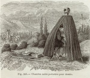
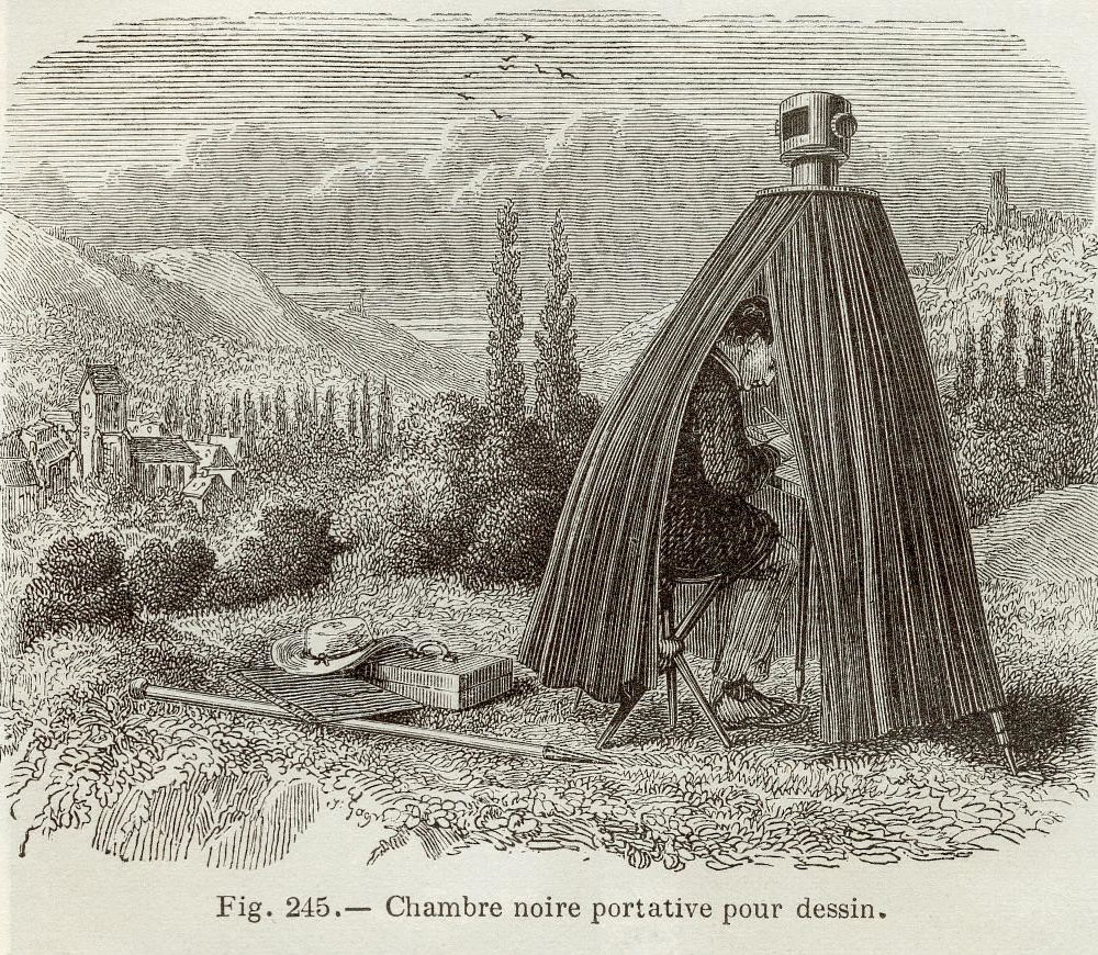
- Fig. 7.
- Chambre noire portative pour dessin, engraving, extract from Adolphe Ganot, Cours de physique purement expérimentale et sans mathématiques... , chez l’Auteur, Paris, 1863, p. 404, n° 245.
[click on the picture to enlarge it]
Amidst such effervescence, it is not entirely surprising to read how Daniele Barbaro, in his Pratica della perspectiva (1569), was one of the first to obtain an image focused on a sheet of paper held at varying distances from a lens inserted into a shutter. Moreover, he discovered that by placing a screen with a hole in its centre to cover the surround of the lens, he improved the effect. Intuitively, Barbaro had found a provisional solution to the problems of spherical aberration causing distortion of the lines near the lens’s periphery, thus showing great skill concerning the focusing of an image.
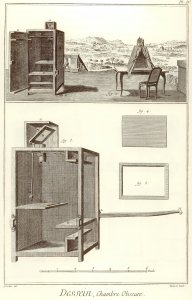
- Fig. 8.a.
- Dessin, Chambre obscure, engraving, extract from Recueil de planches sur les sciences, les arts libéraux et les arts mécaniques avec leurs explications (1762-1772), illustrating the Encyclopédie by Diderot and d’Alembert, pl. IV, n° 147.
[click on the picture to enlarge it]

The second type of technical improvement useful to painters is the construction of a portable camera obscura. These two types of modifications from then on evolved simultaneously, and even in conjunction, since the portability of an instrument meant to be mobile primarily depends on the bulk of the optical device, in which diminution of size should not be obtained at the expense of image quality. In the early 17th century, Henry Wotton, in a letter to Francis Bacon, decribes the camera obscura used by Kepler to make a landscape drawing. The apparatus may be the first to take the form of a small tent, equipped with a lens system at the top; it could be dismantled and oriented in any direction, and thus tranported and settled wherever the draughtsman wishes. Such a type of camera obscura was still sold in the first half of the 19th century, with only a few improvements. (Fig. 7.).

- Fig. 8.b.
- Dessin, Chambre obscure, gravure, extract from Recueil de planches sur les sciences, les arts libéraux et les arts mécaniques avec leurs explications (1762-1772), illustrating the Encyclopédie by Diderot and d’Alembert, pl. IV, n° 148.
[click on the picture to enlarge it]
Though portable, Kepler’s camera obscura still remained a chamber in the full sense of the term, that is, a closed room entirely isolating the observer, or at least the upper part of his body, so as to screen his gaze from daylight. It is anyway the major feature of the tool. In addition to the tent-like model, two variants were also available in the 18th century, as shown on two plates of the Encyclopédie of Diderot and d’Alembert (Fig. 8a. et 8b.): one, called ‘sedan chair camera’ with its two poles to allow for transport ; the other or ‘pavilion camera’, slightly more moveable, meant to be placed on a free-standing table.
- Fig. 9.
- Portable camera obscura with the inscription « A. Canal », Museo Correr, Venise.
[click on the picture to enlarge it]

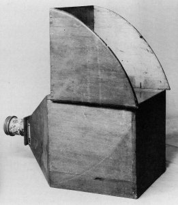
These camerae, however, were still largely considered too cumbersome. Smaller types were perfected, shaped like boxes equipped in front with an optical system inseted into a sliding tube so as to obtain correct focusing, and having a screen fitted at the back, translucent like frosted glass, so as to show the image formed on the reverse (Fig. 2. et 9). In most cases, such camerae were fitted with what would nowadays be called a reflex viewfinder: a mirror inclined 45° enabling the image to be formed on a horizontally-placed screen on the upper part of the box, and to be redressed at the same time, which was a good point for the artist. These first really portable camerae were illustrated by Zahn.
That being said, the purpose of researches over the centuries was to obtain the best possible optical devices, since the image was far from being as good as the reader might imagine. Making a good lens is the main difficulty : the glass should be very homogeneous and transparent, with no bubbles, and perfectly polished. But whatever their efforts, instrument makers could not avoid certain optical problems inherent in lenses, let alone mirrors. Lens systems have the major drawback of presenting imprecise images with blurred outlines. This is beacuse light tends to be decomposed in the margins of the image; also, lines become curved as they are more distant from the centre, and finally the image has too crude colours. This mostly results from aberration phenomena caused by lenses (due to refraction and to spherical form), from the impossibility to focus simultaneously on close and distant objects, and finally from double reflection both on the silvered mirror and the frosted glass. Only with the invention of the meniscus prism by the Chevalier opticians were these optical problems solved around 1823.
1. William Storer’s Royal Delineator

- Fig. 10.a
- Storer’s Royal Delineator camera obscura, 1778 (Science Museum).
[click on the picture to enlarge it]
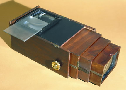
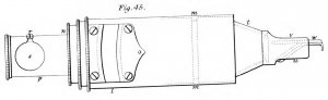
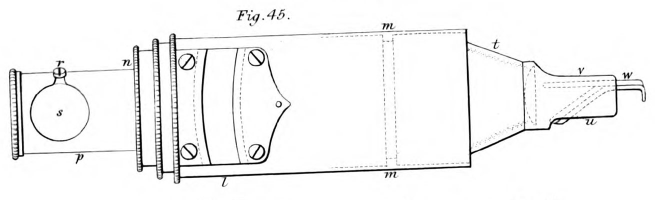
The Royal Delineator was definitely the most complex and the most sophisticated camera obscura around 1778. Cornelius Varley explained its workings : equipped with a second plano-convex lens, it produces a much brighter image, so that the instrument can be used in low lighting conditions (fig. 10.a. et 10.b.).
As the patent registered by its inventor William Storer, a native of Norfolk, emphasizes :
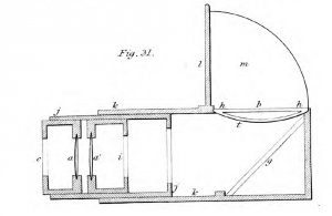
- Fig. 10.b.
- Diagram of Storer’s Royal Delineator, in Cornelius Varley, A Treatise on Optical Drawing Instruments, 1845, detail of plate V.
[click on the picture to enlarge it]

‘being used without assistance of sun in the day-time, and also by candle light, for the drawing of the human face, inside rooms of buildings, also perspectives, landscapes, foliage and fibres of trees and flowers’.
The lens system was such that it produced a larger image on the frosted glass, which was broader than the usual glass panes on the other types of portable camera obscura.
2. The Theatre of the Universe
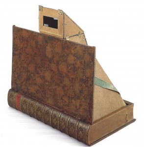
- Fig. 11.
- Camera obscura in the form of a book entitled Théâtre de l’univers, France, around 1750, wood, metal and glass, 56,2 x 55,2 x 36,5 cm (shown unfolded), Los Angeles, Getty Research Institute, Collection Werner Nekes.
[click on the picture to enlarge it]

According to some commentators, the camera obscura could enclose and hold the whole world: it became a real Theatre of the Universe (fig. 11.): such is indeed the name of a folding camera obscura kept at the Getty Research Institute, assuming the shape of a book when folded. ‘The theatre of the universe’ is here written on the spine of the book, like a title.

- Fig. 12.
- Sir Joshua Reynolds’s camera obscura ; it has the form of a book and can be dismantled Science Museum, Londres.
[click on the picture to enlarge it]
The painter Joshua Reynolds owned a similar instrument, now at the London Science Museum (fig. 12.). There is also a third copy kept at the Prints and Drawings Department of the Bibliothèque nationale de France. On a par with books, the camera obscura is the Speculum Mundi, the Mirror of the world, since it shows an Image of the world (imago mundi).
- Fig. 13.
- Abraham Rees, The Cyclopaedia or Universal Dictionnary... , 1820, Plates, vol. 2, p. 199-202 of the PDF. Optigraph by Ramsden, Delineator by Peacock and Edgeworth, Camera Lucida by Wollaston
[click on the picture to enlarge it]

As its name indicates, the delineator allows the user to delineate the outlines of any form that he whishes to copy.
In the first decades of the 19th century, Peacock and Edgeworth’s delineators (fig. 13.) were still in use. With a mirror system, Jesse Ramsden’s optigraph could produce the same effect.
The camera lucida is one of the optical instruments which allow the finest delineation.
Contrary to the Camera Obscura, whose origins are unknown to us, the invention of the camera lucida is well known. Perfected by the English scientist William Hyde Wollaston and patented in December 1806, the principle of the Camera Lucida is the following:
‘While I look directly down at a sheet of paper on my table, if I hold between my eye and the paper a piece of plain glass inclined from me downwards as an angle of 45°, I see by reflection the view that is before me in the same direction that I see my paper through the glass. I might then take a sketch of it, but the positions of the objects would be reversed’.
To correct the reversal, Wollaston invented a double internal prismatic reflection.
- Fig. 14.a.
- Schéma du prisme de la chambre claire de Wollaston (detail of pl. 3, Schémas et dessins de différents types de chambres claires, engraving, extract from Charles Chevalier, Notice sur l’usage des chambres obscures et des chambres claires... , Paris, Vincent et Charles Chevalier, 1829).
[click on the picture to enlarge it]
‘To obtain a direct view, it is necessary to have two reflections. The transparent glass must for this purpose be inclined to the perpendicular line of sight only the half of 45°, that it may reflect the view a second time from a piece of looking-glass placed beneath it, and inclined upwards at equal angle. The objects now appear as if seen through the paper in the same place as before; but they are direct instead of being inverted; and they may be discerned in this manner sufficiently well for determing the principal positions’.
William H. Wollaston, ‘Description of the Camera Lucida’, Alexander Tilloch (dir.), The Philosophical Magazine: Comprehending the Various Branches of Science, the Liberal and Fine Arts, Agriculture, Manufactures, and Commerce, vol. XXVII, Feb.-May, 1807, pp. 343-344, § LVIII.
- Fig. 14.b.
- Chambre claire de Wollaston (detail of pl. 3, Schémas et dessins de différents types de chambres claires, engraving, extract from Charles Chevalier, Notice sur l’usage des chambres obscures et des chambres claires..., Paris, Vincent et Charles Chevalier, 1829).
[click on the picture to enlarge it]
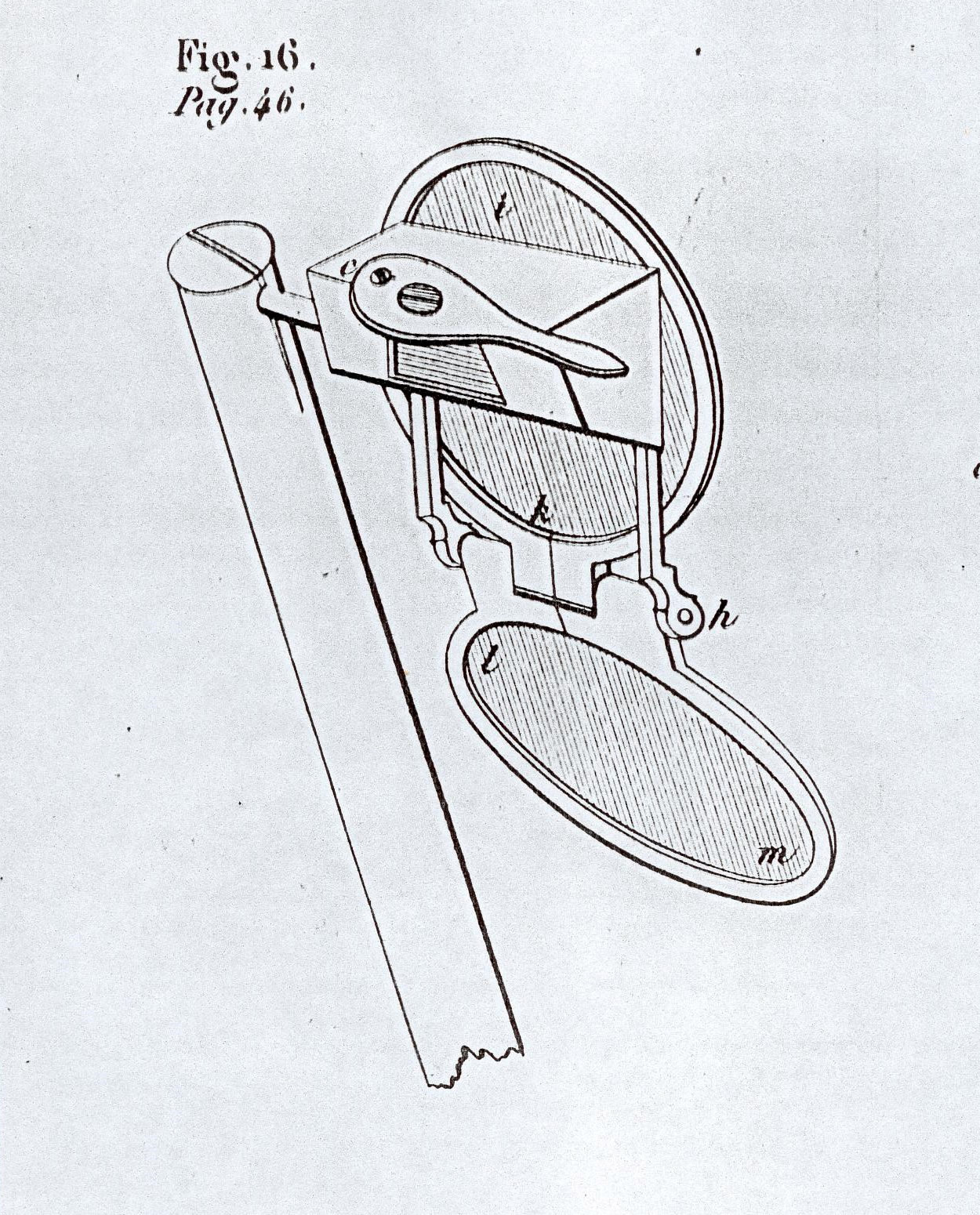
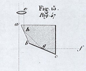
The small piece of glass is a four-faced prism (Fig. 14.a.): a right angle is facing an obtuse angle of 135°; the other two angles form acute angles of 22,5° each. The mirror being placed under the prism on the BC side (see Fig. 14.a.), the f ray is thus reflected in BC towards point G, then in AB towards point H, and finally comes out in E, i.e. towards the eye. The glass is framed in a metal mount with openings (Fig. 14.b.) so as to allow light to enter and come out as shown in the diagram. A telescopic rod with screws is meant to adjust and fix the height of this optical mechanism above a table or a drawing table. The optical is stabilised below by a kind of clamp (Fig. 17b.).Once it is firmly adjusted, the instrument should not move, any more than its stand and the sheet of paper, otherwise the differents parts of the drawing would be disconnected. This is why draughtsmen usually pinned the sheets of paper to keep them firmly fixed on the table.
- Fig. 15.
- George Dollond, Description of the Camera Lucida. An Instrument for Drawing in True Perspective, and for Copying, Reducing, or Enlarging other Drawings, 1830, n.p.
[click on the picture to enlarge it]
The instrument being difficult to use, numerous variants were invented. Among them, Laussedat’s universal camera lucida, those of Abbe, Amici, Albert Chevalier (Fig. 13.), Benoist’s universal camera lucida, Chevalier’s double or twin camera, Nachet’s drawing prism, Alexander’s graphic mirror, Abraham’s instrument….The most widely used camera after Wollaston’s, however, was undoubtedly Amici’s.
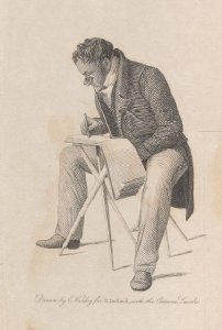
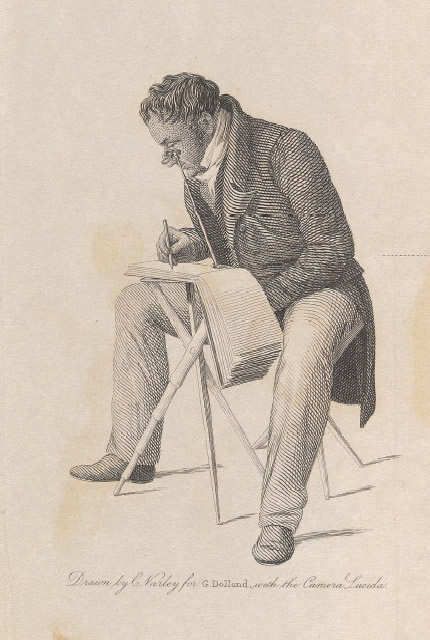
As shown on an engraving by Cornelius Varley (Fig. 15.), it is necessary to have a folding table (convenient for transport) giving the option to make a sketch of a place from any standpoint, as a genuine picturesque traveller would do.
- Fig. 16.
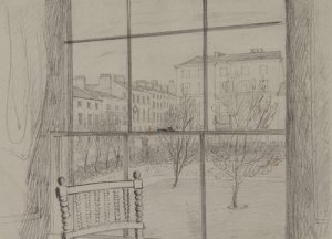
- John Herschel, View from the Hotel Window, Leamington, Warwick, March 1829, 17 x 23,8 cm, n° 554, Graham Nash Collection, Museum of Photographic Arts, San Diego.
[click on the picture to enlarge it]
Sir John Herschel, a major astronomer and scientist (late 18th-early 19th c.), was moreover a skilful user of the camera lucida, with which he produced a large number of drawings (in part kept at the Graham Nash Collection in the Museum of Photographic Arts, San Diego).
When travelling, he used to stop whenever he found an arresting view, so as to keep a memory of it, fixing it rapidly on a sheet of paper, if necessary mentioning in writing the colours and lighting effects which struck him but could not be rendered with the pencil only. Scientifically minded as he was, he even indicated the exact direction of the view he was taking, using a compass.
- Fig. 17.
- Camera Lucida in use drawing small figurine, illustration from the Scientific American Supplement, January 11, 1879
[click on the picture to enlarge it]

This practice enabled him to produce quickly a sketch of a place, which otherwise would have required hours. Townscapes (with particular attention for the monuments) and landscapes (specially for their geological interest), as well as archeological areas (where ruins obviously had a special fascination for him) are his main subjects.
This is how he drew the townscape seen through the hotel window where he stayed during his honeymoon trip with his wife Margaret (Fig. 16.).
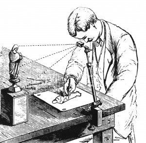
Finally, the camera lucida was used to draw works of art such as statues (Fig. 17.), but also to copy, to trace as it were, already existing drawings or paintings. Edward William Cooke copied his own paintings with the help pf the camera lucida before selling them, so as to keep a trace of them, a practice followed by painters after the invention of photography.
- Fig. 18.
- Diagram of the Cornelius Varley’s Graphic Telescope de, extract from Cornelius Varley, A Treatise on Optical Drawing Instruments, 1845, detail of pl. VIII.
[click on the picture to enlarge it]
In all cases, however, one should remain sensible about all these optical instruments: they certainly help artists and amateurs to draw, but they cannot be sustitutes for the artist’s eye – the choice between what should be drawn and what should be omitted – and for the artist’s hand – the tracing of lines.
As as anonymous author of the Athenaeum wrot in 1830,
- Fig. 19.
- Cornelius Varley, Graphic Telescope.
[click on the picture to enlarge it]
‘Such means are like the railing of a road; they may keep the active traveller on the right course, but they cannot make the lame walk. Let not any one imagine that he can learn to draw, merely by purchasing a Camera Lucida; he might as soon learn music, by merely buying a fiddle’
[Anonyme, ‘The Camera Lucida’, Athenaeum, n° 148, 28 août 1830, p. 540].
Invented by Cornelius Varley, it is one of the most sophisticated tools elaborated for artists (fig. 18.).
Thanks to its optical system, it gives the illusion that the image observed in the instrument lies on the sheet of drawing paper. As with the camera lucida, you ‘just’ then need to delineate it (fig. 19.)... provided you are already able to draw !
III. The frame, framing and picture frames
17th and 18th century amateurs paid special attention to the gradually receding distances in all compositions in drawings, paintings and engravings, and also in gardens, as the Rvd William Gilpin asserts [W. GILPIN, Remarks on Forest Scenery…, II, p. 199 : ‘The fore-grounds are essential to landscape : distances are not’.].
Elsewhere, in his Three Essays, he considers the foreground as a foundation ; it serves as a base on which any image should be constructed. This is why ‘The foreground […] is more so [i.e. essential] than any other part in forming a composition’ [William GILPIN, Three Essays: on Picturesque Beauty; on Picturesque Travel; and on Sketching Landscape: To which is added a Poem, on Landscape Painting, 2nd ed., London, R. Blamire, 1794, p. 69].
Such views were commonplace in the late 18th century, since they can be traced in France, in the writings of Marquis René-Louis de Girardin, in his treatise on gardening:
« Le cadre d’un tableau sur le terrain est produit tout naturellement par son avant-scène ou les masses de devant »
[René-Louis de GIRARDIN, De la composition des paysages ou Des moyens d’embellir la Nature autour des Habitations en joignant l’agréable à l’utile (1777), suivi de Promenade ou itinéraire des jardins d’Ermenonville (1811), rééd. Champ Vallon, Coll. Pays/Paysages, Seyssel, 1992, p. 39].
The image is thus less composed by cutting out and framing a subjet, positioning it to design an image defined by the limits of the field or support of the picture, than by circumscribing part of a landscape in order to make it rest on a frame.
The frame of a forestage gives a stand to the view and confers stability on it. Or, as it might be said, the frame is an “U”, and even a “__” (conversely, suppressing the foreground produces a vertigo effect on the spectator, which was exploited by Romantic painting generally speaking, and more particularly by Caspar David Friedrich).
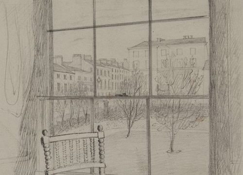
It is fairly significant that the engaving in the Encyclopédie illustrating the camerae obscurae shows them on a terrace, with the landscape as a background, framed by a balustrade and a balcony (fig. 8.a.).
Such a use of the frame explains why, to conclude, all users of Claude glasses seem at the time to have been indifferent to their shape or format — round, rectangular, oval…. At the time, the forceful effect given by the foreground to the composition confers less significance on the form of the frame as outline.
B. Framing effects and the sublime: William Chambers’s recycling of the suburbs
William Chambers reminds us that the vicinity of towns was felt as particularly horrible in the late 18th century. In order to transform such landscapes of urban peripheries, which the beginnings of industrialisation and the practice of public executions had made terrifying, the architect proposed to build large frames through which ramblers could watch the horrible suburban spectacles.
Such devices would have enabled the viewer to distantiate the terrible scenes, to neutralise them by removing any possible danger, and thus to transform them into ‘pleasureable horror’, or into sublime landscapes according to Edmund Burke. It is an appropriation process, based on recycling (recycling is also one of the mechanisms of kitsch, and also of capitalism [Jean-Claude Lebensztejn, ‘Photorealism, Kitsch, and Venturi’, Aaron Vinegar, Michael J. Golec (editors), Relearning from Las Vegas, Minneapolis, University of Minnesota Press, 2009, p. 65 : ‘Capitalism had learned the art of accommodationg its leftovers. What it still had to learn was how to recuperate all of its scraps, without remainder’]).
‘England abounds with commons and wilds, dreary, barren, and serving only to give an uncultivated appearance to the country, particularly near the metropolis: to beautify these vast tracts of land, is next to an impossibility; but they may easily be framed into scenes of terror, converted into noble pictures of the sublimest cast, and, by an artful contrast, serve to enforce the effect of gayer and more luxuriant prospects.
On some of them are seen gibbets, with wretches hanging in terrorem upon them; on others, forges, collieries, mines, coal tracts, brick or lime kilns, glass-works, and different objects of the horrid kind: what little vegetation they have, is dismal; the animals that feed upon it, are half-famished to the artist’s hands; and the cottagers, with the huts in which they dwell, want no additional touches, to indicate their misery: a few uncouth straggling trees, some ruins, caverns, rocks, torrents, abandoned villages, in part consumed by fire, solitary hermitages, and other similar objects, artfully introduced and blended with gloomy plantations, would compleat the aspect of desolation, and serve to fill the mind, where there was no possibility of gratifying the senses’.
William Chambers, A Dissertation on Oriental Gardening, London, Almond, 1773, p. 130-131.
IV. Science Museum, London
Most of the optical instruments mentioned here belong to the Science Museum in London.