
Perspective methods
- Elevation and perspective
- Perspective: the vanishing point
- Perspective: the horizon line
- Perspective: proportions
Elevation and perspective

- Somerset House
- Chambers, elevation for the river front of Somerset House (Victoria and Albert Museum Picture Library)
[click on the picture to enlarge it]
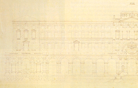
An architect would prepare his designs as plans and elevations: in an elevation, the house would be viewed from the front ; the parallel horizontal lines of the bands and cornices between the storey would remain drawn as horizontals.

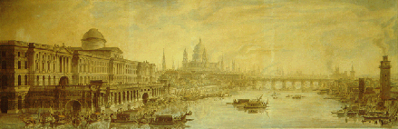
- View of Somerset House
- Jean-Louis Desprez, View of Somerset House (Yale Center for British Art/ The Bridgeman Art Library)
[click on the picture to enlarge it]
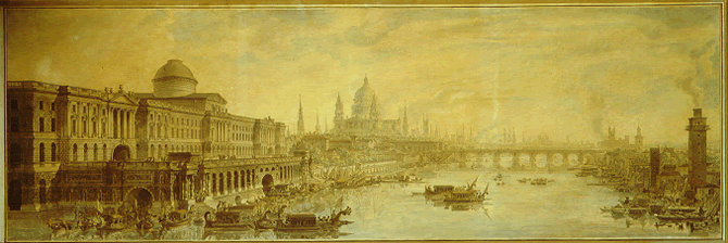
A draughtsman would prefer an oblique perspective view: the house is viewed from the angle, the parallel lines of the storeys are drawn as obliques converging towards a vanishing point.
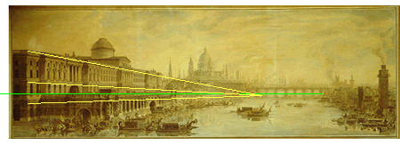
Perspective: the vanishing point
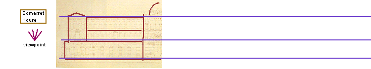
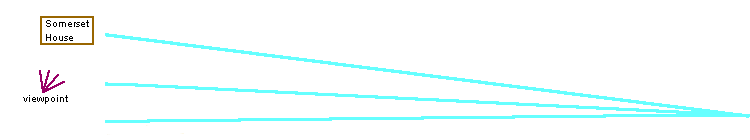
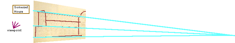
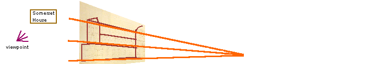
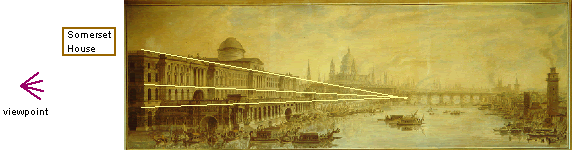
In Desprez’s perspective drawing (bottom), they converge on a fairly close vanishing point.
Two intermediary positions for the vanishing point and receding lines have been plotted here. To see the corresponding gradual perspective distortion of the building, click on the receding lines.
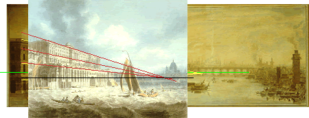
Perspective: the horizon line
- View of Somerset House
- Jean-Louis Desprez, View of Somerset House (Yale Center for British Art/ The Bridgeman Art Library)
[click on the picture to enlarge it]

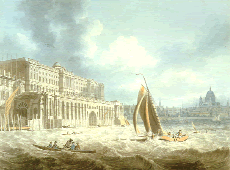
- Somerset House
- Edward Dayes, Somerset House, c.1790 (The Courtauld Gallery, London/ Bridgeman Art Library)
[click on the picture to enlarge it]

![[click on the picture to enlarge it]](IMG/gif/4.gif)
Draughtsmen could select a fairly high point of view and horizon line (where horizontal receding lines converge), like Desprez, who placed his supposed observer at the height of the terrace or they selected a low point of view and horizon line, like Dayes, who placed them just above the water, so that the building dominates his supposed observer placed almost as if he were in a boat on the Thames.
- Jean-Louis Desprez
- Edward Dayes
Dayes also practised frontal perspective, for instance in his View of Hanover Square
Perspective: proportions
Pulteney Bridge: Turner’s problem
The painter J. M. W. Turner, best known for his romantic landscape paintings, used Pulteney Bridge (Bath) in his lectures as Professor of Perspective at the Royal Academy, to introduce the students to the problem of the division of a projected line according to given proportions.
Adam’s buildings, characterized by geometrical shapes of regular proportions, were particularly well suited for this demonstration.
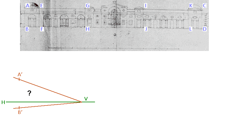
The problem: Suppose we have the elevation of a building ABCD divided into several sections having BF, FH, HJ, JL, LD as measurements,and we wish to project it in oblique view so that the horizontals AC and BD become receding lines starting from A’ and B’ and converging on a horizon line on vanishing point V, how shall we space the verticals which are the projection of AB, EF, GH, IJ, KL, CD, so that the proportions between BF, FH, HJ, JL, LD are preserved?
First we establish a horizontal “measuring line” above the proposed projection and a receding line towards V...
![[click on the picture to enlarge it]](IMG/gif/5.gif)
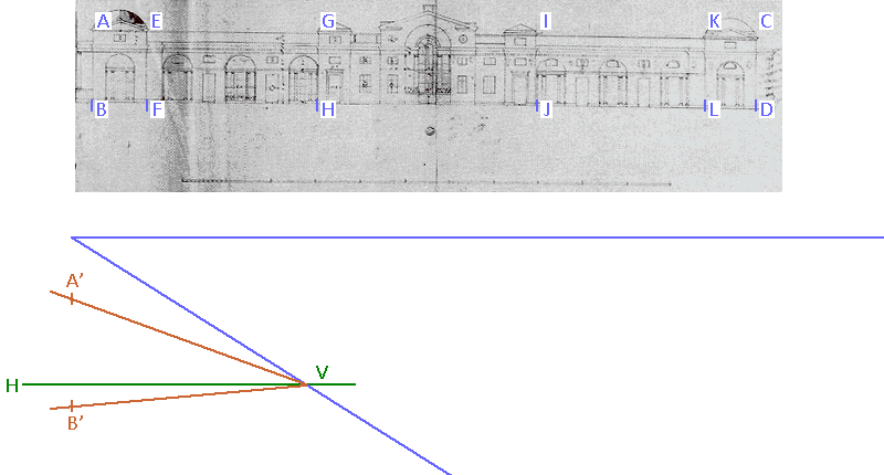
...then from the division markers B, F, H, J, L, D, we drop verticals on the measuring line, which gives points B1, F1, H1, J1, L1, D1 ...
![[click on the picture to enlarge it]](IMG/gif/6.gif)
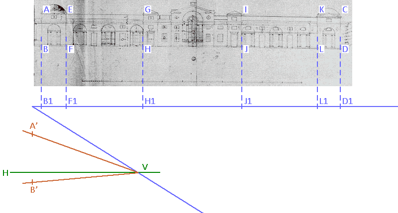
...then from measuring point M on the horizon line draw MF1, MH1, MJ1, ML1, MD1...
![[click on the picture to enlarge it]](IMG/gif/7.gif)
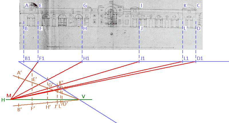
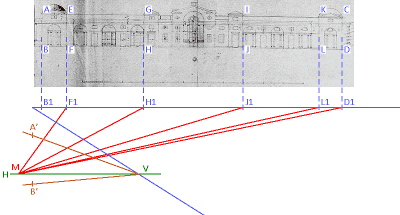
...and at the point where they cross the oblique B1 V draw verticals which are the projections of the verticals of the elevation.
![[click on the picture to enlarge it]](IMG/gif/8.gif)
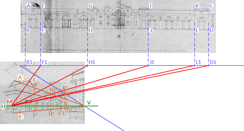
We can now draw the rest of the bridge in this wireframe structure...
![[click on the picture to enlarge it]](IMG/gif/9-2.gif)
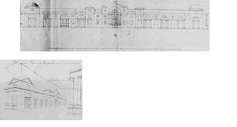
This is Turner’s finished drawing (c.1815, Turner Bequest CXCV 113)
![[click on the picture to enlarge it]](IMG/gif/10.gif)